Often, manufactured part measurement processes are impacted by misalignment between the measurement device and the part itself. Most measurement devices acquire their data in a grid or square format. Most of the time, the part being measured by these devices has its own orientation and structure to the features to be measured. A great example of this is a patterned semiconductor wafer. It is round in shape, but the important features that need to be measured are laid out in a grid format. If the measurement tool being used is not aligned properly to the wafer’s grid pattern, finding specific measurement locations can be challenging, and stitching large image fields can be next to impossible.

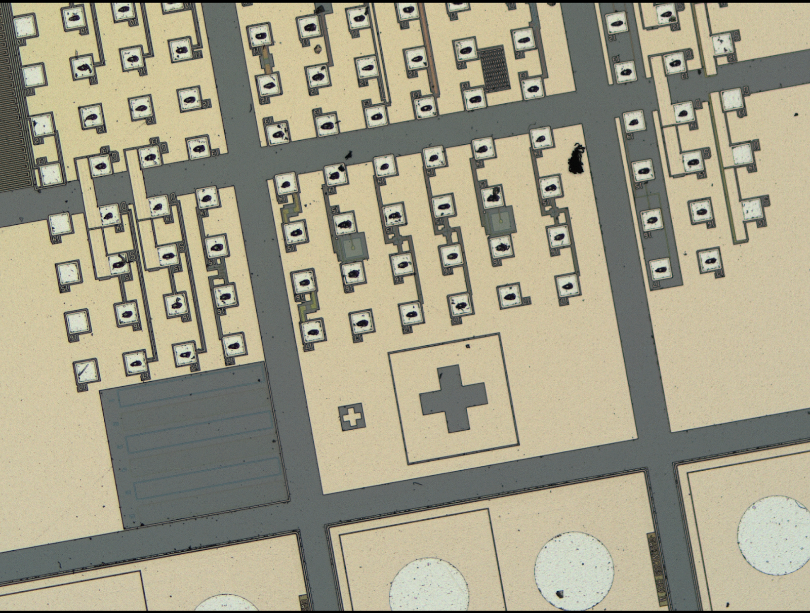

Figure 1: A patterned semiconductor wafer shown at the top. The two images on the bottom show a measurement device’s live view of a particular area on the wafer. The lower left image shows the wafer at an angle while the lower right shows the wafer rotated and aligned with the measurement device.
There are helpful alignment techniques that can be used to “square up” the part and measurement device. Furthermore the use of motion control makes rotational alignments robust and easy. Now, let’s look at the most popular techniques.
Using Transformed XY Motion
Most high-resolution measurement tools already have access to XY motion as a way of extending the measurable area outside of the small field of views available from the measurement device. We can use this same XY motion and a simple transformation in order to address part rotation concerns. Here, we can calculate the angle offset between the measurement field of view and the part, apply a transformation to the X and Y axes, and then command the X and Y motion stages to traverse parallel to the new transformed axes.

Figure 2: Transformed X and Y coordinates according to a calculated rotation angle.
This allows the user to navigate across the part much easier. Now the live image from the measurement device will be able to follow the part’s geometry. However, stitching of individual measurement zones is still a challenge with this implementation. This is because the images must be matched in X’ Y’ space when in reality they are taken in X and Y space. See below for what this resultant stitched image ends up looking like. You can see that the individual images need more overlap with each other, and there is a maximum threshold for how misaligned the part is before the stitching algorithms run out of search capabilities and fail.

Figure 3. Individual images on the left hand side after stitching. Notice how the individual dies on the wafer do not line up, due to the larger rotation angle. The same area with a smaller rotation angle allows the images on the right hand side to stitch properly. Notice how the dies now line up.
Using Rotation Stages
When possible, the best approach is to actually rotate the part normal to the field of the measurement device. This will allow for easier navigation across the part as well as much simplified stitching when larger measurement fields are needed.
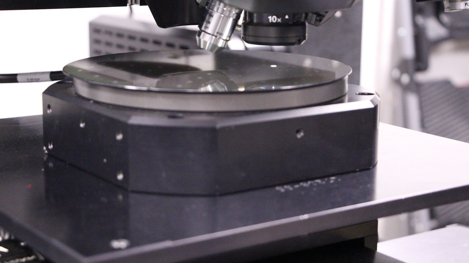
Figure 4: Showing a wafer mounted to a rotary stage underneath a high resolution microscopy system. This rotary stage is used to align the wafer to the microscope’s field of view.
The best way to explain the benefits of this approach is through video.
Your Go-To Partner for User Interface
We are experts at applying motion control techniques to enable advancements in measurement processes. We have purpose-built software tools that incorporate these techniques into easy-to-use steps for our users. Contact us to learn more about our tools and how your measurement process can benefit.

Figure 5: A software user interface for easy part rotation.