The VR microscope from Keyence has built in larger stage control and image stitching capabilities. This is useful for measuring larger parts that are greater than 200mm in any one XY dimension. There are a few important considerations to keep in mind when performing measurements over a larger area with this microscope.
1. There is a max stitched area size that can be achieved. This area is defined by the number of images and ultimately pixel count.
2. If the stitched area size is too large the software will apply a compression algorithm to limit the file size and reduce the pixel count.
3. The VR software comes with settings to help you maintain high resolution over larger measurement areas.
Maximum stitching area
The VR software allows for up to 320 individual images to be stitched together. The magnification that you are operating at will dictate how big each individual image will be when acquired. The stitching algorithm uses a 15% overlap in-between the images which means that the largest area that can be stitched is 310mm x 300mm when operating at 12x magnification (the lowest magnification). The area can be configured so that more images are taken along either the X axis or Y axis. The maximum number of images that can be taken in any one direction is 25. Therefore, and for example, you could acquire a 500mm x 50mm area by configuring your stitch to 25 images x 4 images in size at 12x magnification.
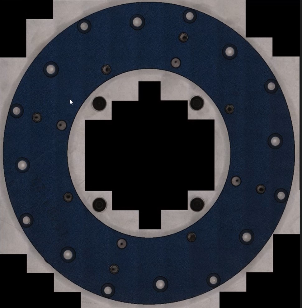
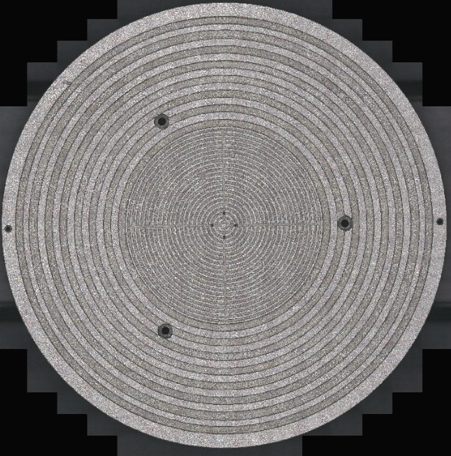
When using the map area to create a stitched image, the operator can select exclusion zones where images would not be taken (see the black areas in the image above). Note that each exclusion zone still counts towards the max number of stitched images that can be combined into one large image. However, using exclusion zones will save time since the measurement process does not need to stop and take data at these locations.
The time to acquire a large number of images and stitch them together is another useful data point in the decision to buy a VR system with a larger stage. To stitch a 300mm x 300mm area at 12x magnification, the system would take approximately 30 minutes. The smaller the area the faster the measurement process would be.
The larger the stitched image the less pixel resolution you will have
The stitching algorithm will allow you to stitch up to 320 images together. But that does not mean that you should. Nor does it mean that it will work for your application. When the number of images to be stitched approaches certain amounts, the stitching algorithm will automatically apply an image compression technique to reduce the data file size. When the image compression is applied the pixel count of the resultant stitched image is reduced. Pixels equate to resolution, and therefore image compression leads to less resolution. This can be seen in the following example scenario.
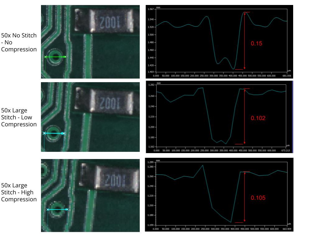
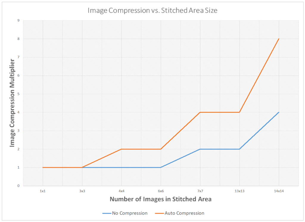
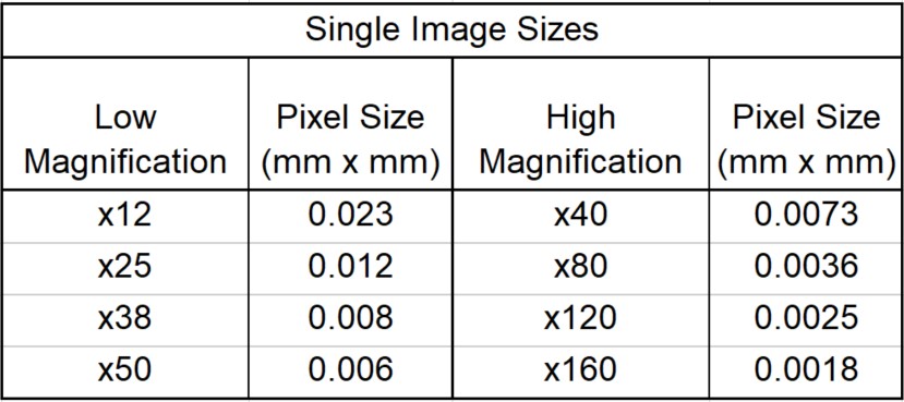
The VR software has image settings that define how much compression is used when stitching images together. There two main settings are Auto Compression and No Compression. Auto Compression will optimize the image for the smallest file size which introduces more compression. No Compression optimizes for higher resolution which results in a larger measurement file size. There is still image compression occurring even if the No Compression setting is selected. Below is a chart that shows how many images can be stitched together with either setting before image compression is applied to increase the pixel size. Again, when pixel size increases it means a loss in image resolution.
The solution to achieve high resolution data over larger areas
Option #1 – Use the settings menu to choose less compression
If your data management system can handle a larger file size, simply selecting “no compression” in the list of image compression options will give you approximately 2x the pixel resolution. There are still cutoffs where compression is automatically applied to the image regardless of selecting the No Compression setting or not. These cutoffs occur at a distinct number of images that are to be stitched together. For example: a 6×6 stitched image will have full resolution when using the No Compression setting, but when you jump to 7×7 the pixel size increases and the image is compressed. This option should be combined with Option #2 if a larger area needs to be covered with higher resolution.
Option #2 – Use the duplicate scan function
Using the Duplicate Scan Mode feature of the VR microscope allows the user to specify multiple smaller stitched area regions and overlap or relate them together. This allows the operator to select the stitched area that provides the pixel size
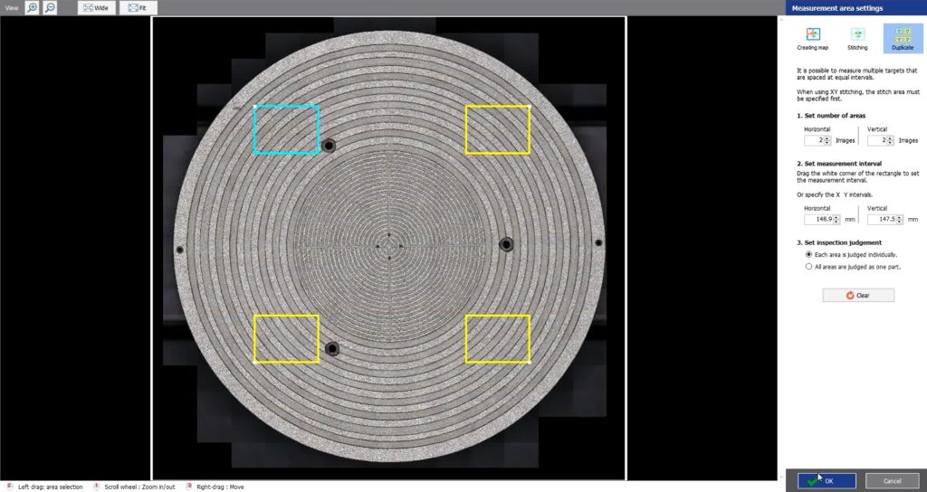
In Duplicate Scan Mode the user can specify up to 168 individual boxes that can amount to any number of stitched images inside of them. Here are two examples of Duplicate Scan properties and measurement execution time for a 300mm diameter area.
1. An array of 8 x 11 boxes with 4 individual images stitched into one large image for each box. At 12x this measurement process is accomplished in 34 minutes.
2. This example will maintain the coverage area from example #1, but using a higher magnification for greater resolution. An array of 8 x 11 boxes with 16 individual images stitched into one large image for each box. At 25x magnification this measurement process is accomplished in 1.5 hours.
In summary, measuring larger areas across a part’s surface is often needed. When doing so, image compression and resolution loss should be top of mind. Luckily, this particular microscope (Keyence VR) has built in tools to help the users solve the issues caused by image compression algorithms.
Using the information above, it is the user’s responsibility to select the appropriate image size based on the required pixel resolution needed to solve the application. Keyence and Peak Metrology should be consulted to assist with the selection of that scan mode that would work best. Furthermore, Peak Metrology will help calculate maximum stitching areas and maximum stage travels possible on an application by application basis.
For more guidance and consultation on selecting the right positioning system for your microscopy application reach out to us.