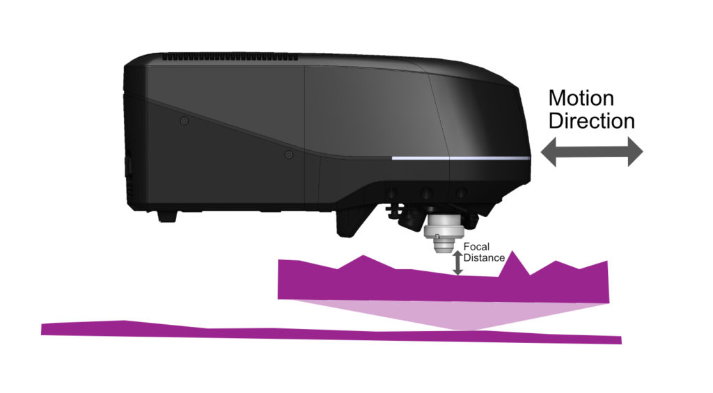
Covering Keyence VK-X series scanning microscopes.
Scanning microscopes can be difficult to optimize over large surface areas since their measurement depth of field is so small. If the surface you are trying to measure has a slight tilt to it, or if there are localized height differences across it, it will be hard to find the right focal height for your microscope to operate at. There are 3 main benefits of utilizing a height sensor in addition to your scanning microscope.
- You will find the microscope’s focus faster and shorten measurement times
- You will be able to use a fixed set of measurement parameters to better correlate data from measurement to measurement
- You will avoid microscope lens collisions at high magnification
Microscope limitations that a height sensor helps solve
Precision confocal and digital microscopes have a limited focal depth. Especially when it comes to higher magnifications used to create higher resolution images. This is a fundamental property caused by the optical design required to reach those fine resolutions. Depending on what your measurement process can tolerate there are a few potential downsides to these optical limitations.
#1 Your microscope not being in focus requires the use of a timely “Auto Mode” focus routine.
Autofocus routines are great for getting the microscope back into focus without any operator involvement. However, they require the microscope to be “close enough” to the surface for the autofocus to work. Additionally, they take time to execute. “Auto Mode” refers to the Keyence VK-X microscope’s ability to set the focal range of the measurement automatically, and then instruct the Z axis to move throughout it’s scan range. Over the course of many measurements on a large surface the time it takes to execute the Auto Mode at all points can add a significant amount of measurement time to your process. When using a height sensor the measurement range can be set to tighter/faster range while reducing the time it takes to autofocus.
Overall reductions in measurement time vary based on total number of measurements, measurement parameters used, and travel distance between measurements. However, it is typical to see 30-50% percent reductions in measurement cycle time when height sensors are employed appropriately.
For Example, a 25 location measurement routine on a flat surface (<25um localized flatness) took 21 minutes to measure total while using the Auto Mode routine. That same measurement routine with a height sensor took 15 minutes. The height sensor reduced the total measurement routine by 33%.
There are different types of focus routines. Some simply find a single focal depth for the microscope. Others, like the Keyence VK-X microscope’s Auto Mode, find both the lower and upper surfaces and set the measurement range accordingly. The downside of the Auto Mode routine is that it takes longer than a single focal point autofocus routine. Furthermore, if the variation in the part’s surface height is outside of the Auto Mode’s search range it will lead to failed measurements (measurements that are not in focus).
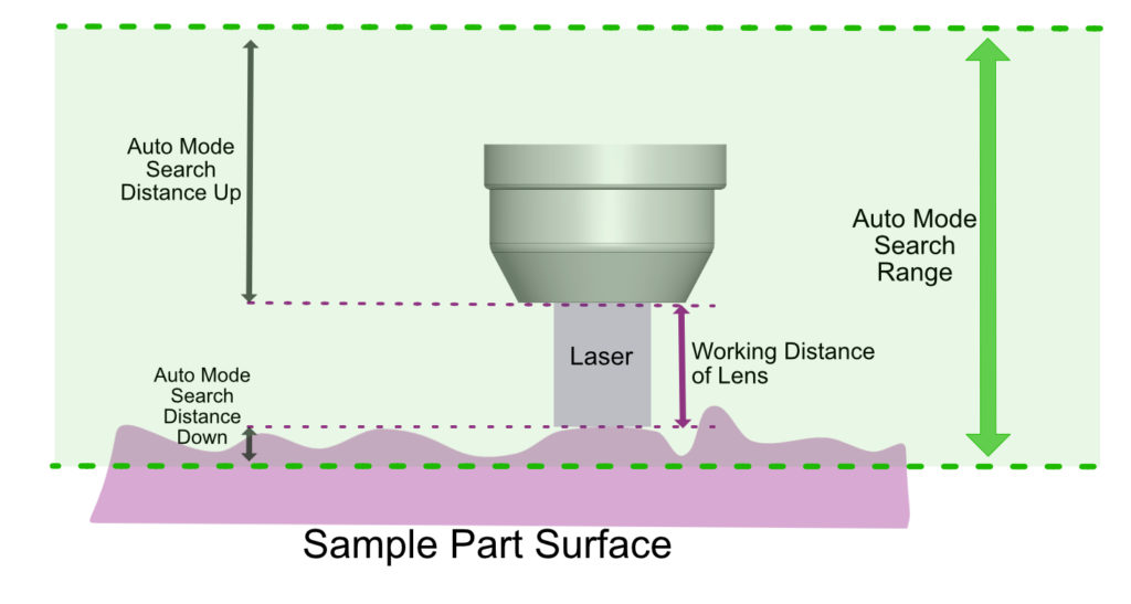
For Example, when using a 50x lens there is only ~75um of downward search range when using Auto Mode. This means that if your sample surface is lower than 75um than the previous measurement surface level the Auto Mode search routine will fail to pick up the full focal range needed. Does your surface have more than 75um of height variation in it? This includes both the local height variation of the surface itself and the global height variation due to sample mounting surface flatness and tilt.
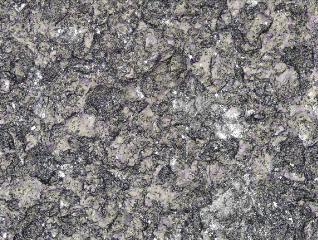
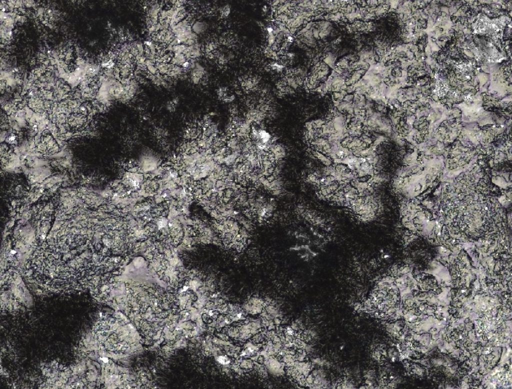
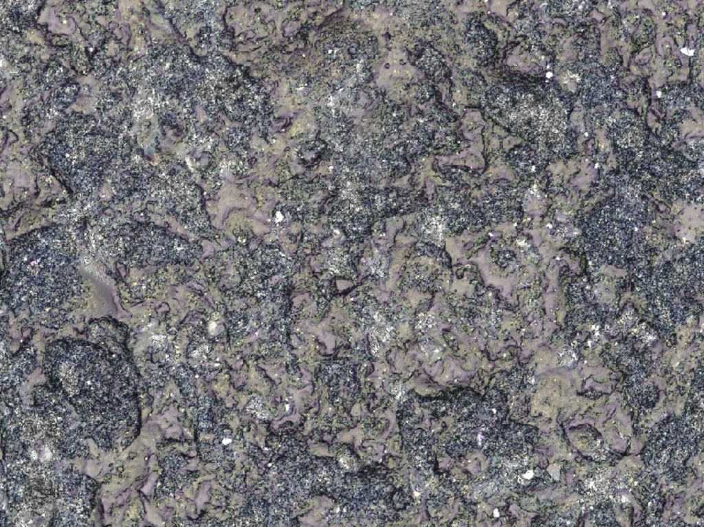
These two images are taken using the same microscope at two different locations on the part surface. One is in focus (left) and one is out of focus (right). The black pits shown in the image to the right indicate that it is out of focus. The right focus routine or a height sensor focal distance optimization routine would have made sure the image was in focus.
#2 Your microscope’s inherent autofocus routine may set new measurement parameters without your input.
Autofocus routines may specify certain measurement parameters as well. These parameters include measurement depth of field and lighting/intensity settings. These are important settings, and if you are trying to avoid changes to known good measurement parameters then using an autofocus routine could overwrite your ideal settings. This can cause some images to to be brighter or darker than previous images, or it can also change how much depth of surface you are actually taking data over. This means measurement variability from location to location on your surface, and that is often undesirable.

Both of the images above were taken using the same microscope on the same part surface. Both were taken at different locations on that part and using an “auto” mode that set both focal depth and the intensity of the image automatically. Notice how both of the images are in focus but one is darker than the other. Fixing the intensity of the image constant would have made sure that both images had the same coloration.
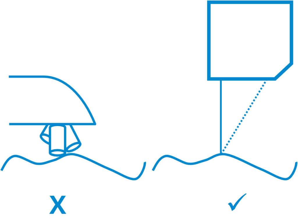
#3 Your microscope lenses may operate at shallow working distances that create possible surface crash conditions.
When using high precision microscopes and high magnification lenses the working distances are specified in microns. These ranges can get down to around 200 microns. If the surface being measured varies by more than a few hundred microns it is possible for the lens to come into contact with the surface. This becomes a larger issue when talking about large surface areas of hundreds of millimeters across. It’s likely that the part holding fixture or the part itself has more height variability than the higher magnification lenses can operate at. In this case pre-mapping the surface using a height sensor will alleviate the potential crash conditions that may exist.
What is a height sensor?
A height sensor is an additional sensor that rides alongside of your microscope. It uses different measurement principles based on the model and vendor that is selected. In practice, most of these height sensors are specified as single point units so that they can be used to measure the distance between the center of the microscope’s field of view and the surface being measured.
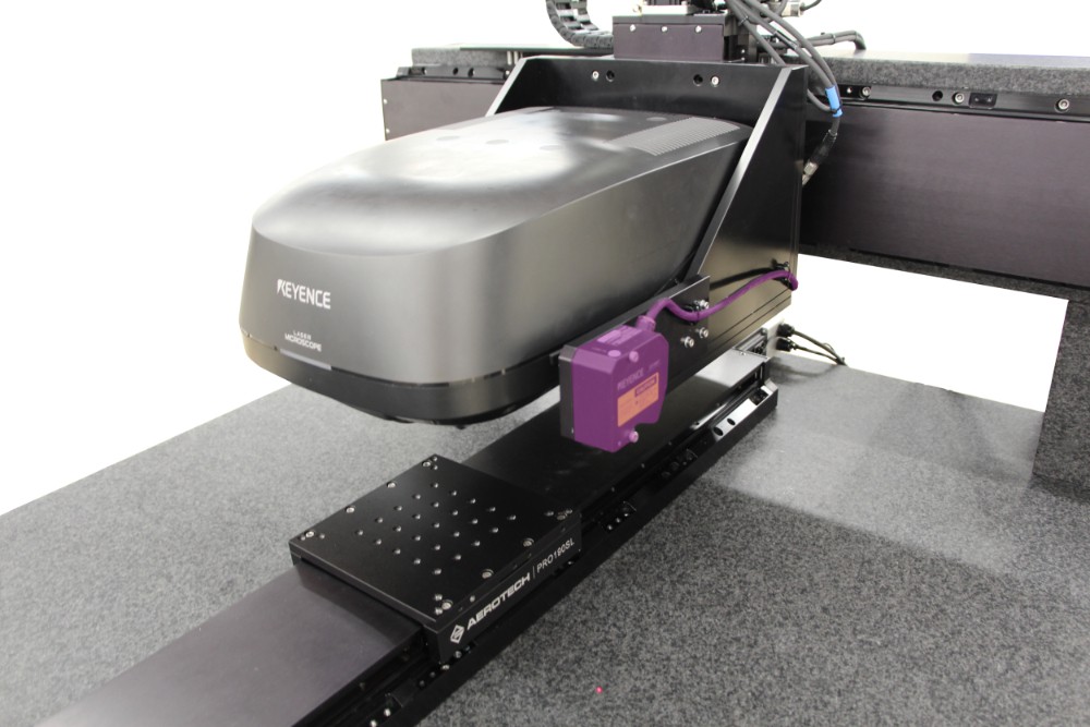
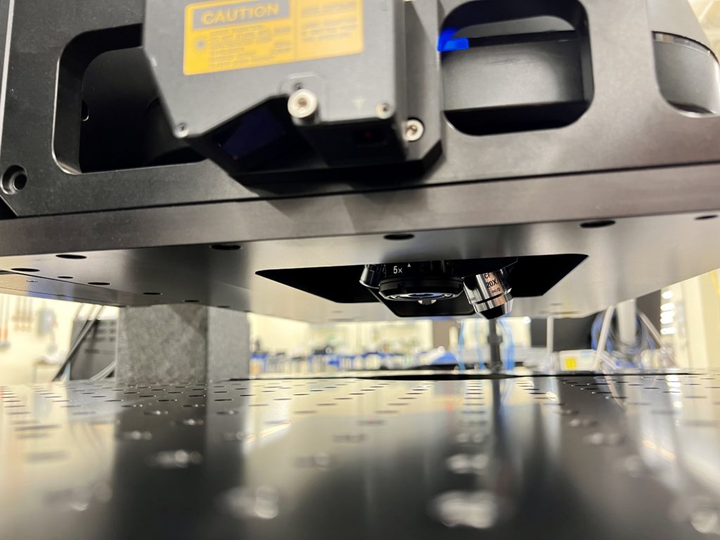
These two images show height sensors that sit alongside the microscope. Both height sensors are at a fixed offset in XYZ from the center of the measuring field of the microscope. They also have longer measurement working distance than the microscope objectives. This means that the microscope objectives will be lifted up before the height sensor takes its measurement.
How a Height sensor works
The height sensor goes to all XYZ locations where a measurement is specified. It then takes an absolute measurement value of the height of the surface at that location. From there, the software compares that value to the known offset between the height sensor and the microscope’s objectives in physical space. This comparison calculates a correction factor that will be used to tell the microscope where the surface actually is compared to where the operator thought it was.
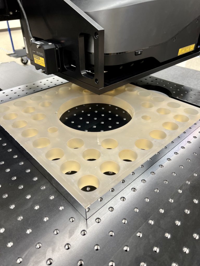
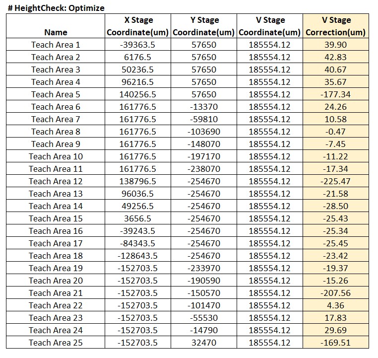
Showing an example part surface that was programmed for a measurement routine. 25 locations across the surface of the part were programmed in XYV space (V is the vertical stage that carries the microscope, and adjusts its height according to the correction value). The V Stage Correction values highlighted on the right hand side of the table shows how far the surface deviated across the 25 locations. These values will command the V axis to move up and down accordingly before the microscope is dropped into position.
Video overview showing the solution in action
For more guidance and consultation on selecting the right positioning system for your microscopy application reach out to us.