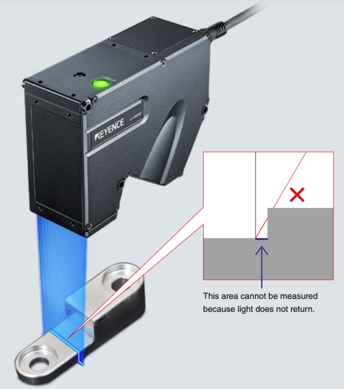
Shadowing occurs when the laser is blocked by a part surface while trying to return to the sensor head.
The problem: Missing surface data
The triangulation principle, such as the one used by laser measurement devices, often has a limitation when it comes to measuring surfaces with tall features. These tall features obstruct the outgoing laser line which causes missed suface data. This missing surface data is often referred to as loss due to shadowing.
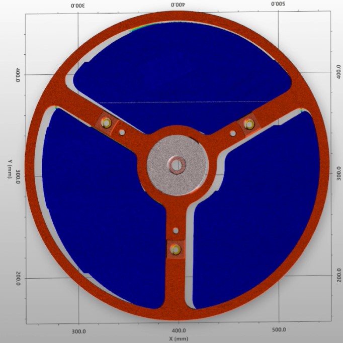
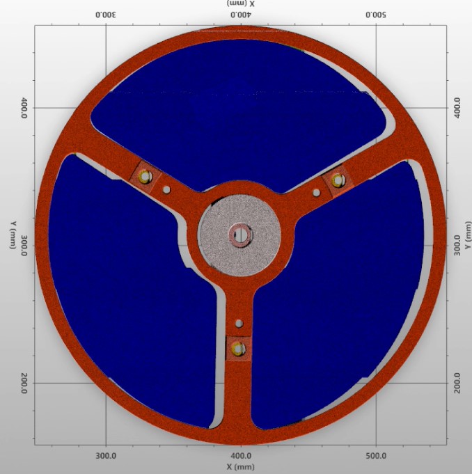
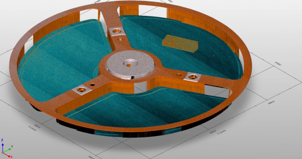
When attempting to digitally construct the surface of this part using a laser triangulation sensor, there are shadowing effects caused by the angle of incidence. The image on the left shows a sensor using an outgoing beam aimed towards the left. Notice the missing data just to the right of the tall sidewall features. Similarly, the image on the right is of the surface measurement data when the sensor’s outgoing beam is aimed towards the right. This data is missing on the oposite side of the sidewall features.
The solution: Gather surface data from both directions to avoid shadowing
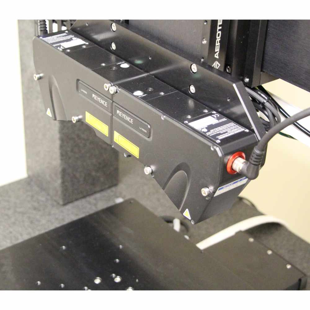
The shadowing effects caused by the laser triangulation principle are unidirectional. We can reorient the sensor 180 degrees and take a second scan of the same part surface in order to gather the missing data. Another way to solve this problem is to add a second sensor that is pointed in the opposite direction. The latter is the ideal solution since it does not require a second surface scan which would increase the time to take the measurement data.
Using a back-to-back pair of laser triangulation sensors will eliminate the shadowing caused by uni-directional scanning. Each sensor acquires data from the opposite direction, effectively removing the impact of sensor shadowing.
Important considerations
A few important considerations need to be made in order to reconstruct the surface measurement data without any loss and with sufficient precision for the measurement tolerance.
- The sensor(s) used to eliminate the shadow areas must be aligned to each other with enough precision. If the sensors are not aligned to each other then combining the data into a single data set will result in data alignment errors. The combined data set assumes that both sensors are aligned perfectly, and that they are scanning the same location on the part. When this is not the case the misalignment will show up as error artifacts in the data.
- The data needs to be parsed and combined in a manner that represents a full surface scan. A typical method to do this is to collect full sets of surface data for both sensors and then to apply a set of rules.
- If both sensors return a surface measurement value at a specific location those values are averaged.
- If only one sensor returns valid measurement data at a point in space then that sensor’s value is taken alone, and not averaged with the other. This rule is where the shadowing is taken care of since one of the two sensors will be blocked from returning a valid point in these areas on the part’s surface.
Conclusions
Using back-to-back laser line scan sensors will anable the measurment tool to see the shadowed areas on the part.
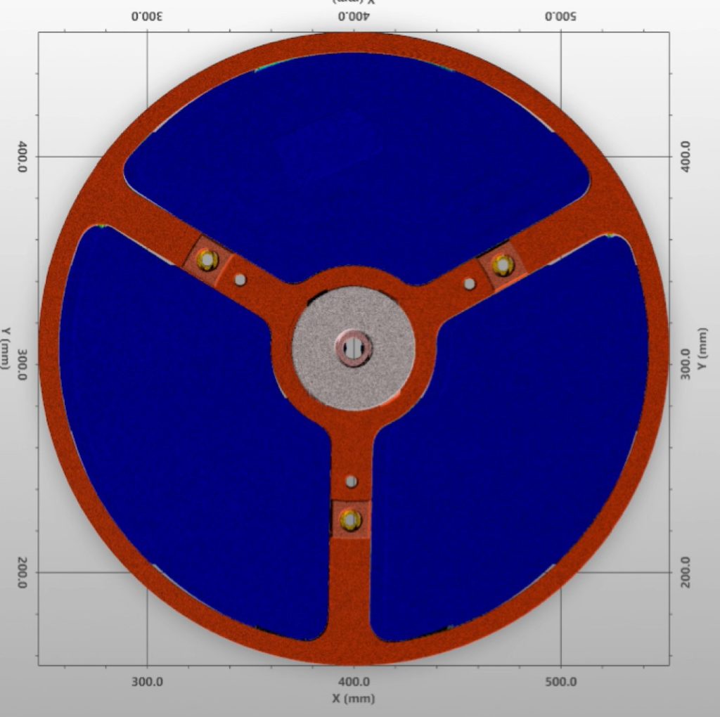
Showing the resultant data set of two sensors operating in back-to-back configuration. There are no missing areas of data for surfaces normal to the sensor.
Video overview showing the solution in action
For more guidance and consultation on selecting the right positioning system reach out to us.