This paper explains floor vibration and how to measure it. It also shows the performance of laser confocal microscopes over a variety of floor conditions.
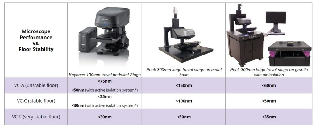
Quick reference: Use this lookup table to determine the hardware you need
Not sure How stable your floor is? Let us measure it!
Floor vibration characteristics cause large swings in microscope performance on the nano-scale
Floor vibration characteristics may cause swings in microscope performance on the nano-scale.
There are many factors that lead to better or worse vibration stability. These factors include the table being used to support the microscope stage, the size of the microscope stage, and the floor vibration levels, among many other factors. Furthermore, acoustics and the vibration caused by the microscope lens motion will impact the noise floor of the measurement data.
What does floor vibration look like?
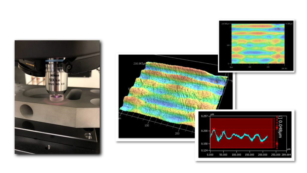
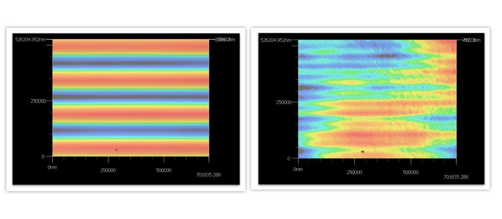
Floor vibrations show up as image shake in the live view of the microscope. They appear as “waves” that typically run North and South on the image. The images below show the worst case scenario. By placing an optically flat surface under the microscope and using the highest magnification (150x) the disparity among the two images is the most pronounced. When moving the tool from a good stable floor to a poor unstable floor the change in vibration magnitude is pronounced.
Many applications will not be affected by floor vibrations. For ones like the application shown below it is an important factor that must be recognized. There are multiple ways to eliminate the effects of this vibration.

Showing the live view image from a VK-X microscope at 150x magnification.
Showing the live view image from a VK-X microscope at 150x magnification.
Floor vibration can be quantified
The floor that precision metrology equipment sits on is a primary contributor to measurement stability. These floors can be measured by seismic accelerometers to expose their underlying vibration characteristics. Of particular concern is the vibration amplitudes at various frequencies. A standard method of classifying floor vibration levels is known as the Vibration Criteria Chart.
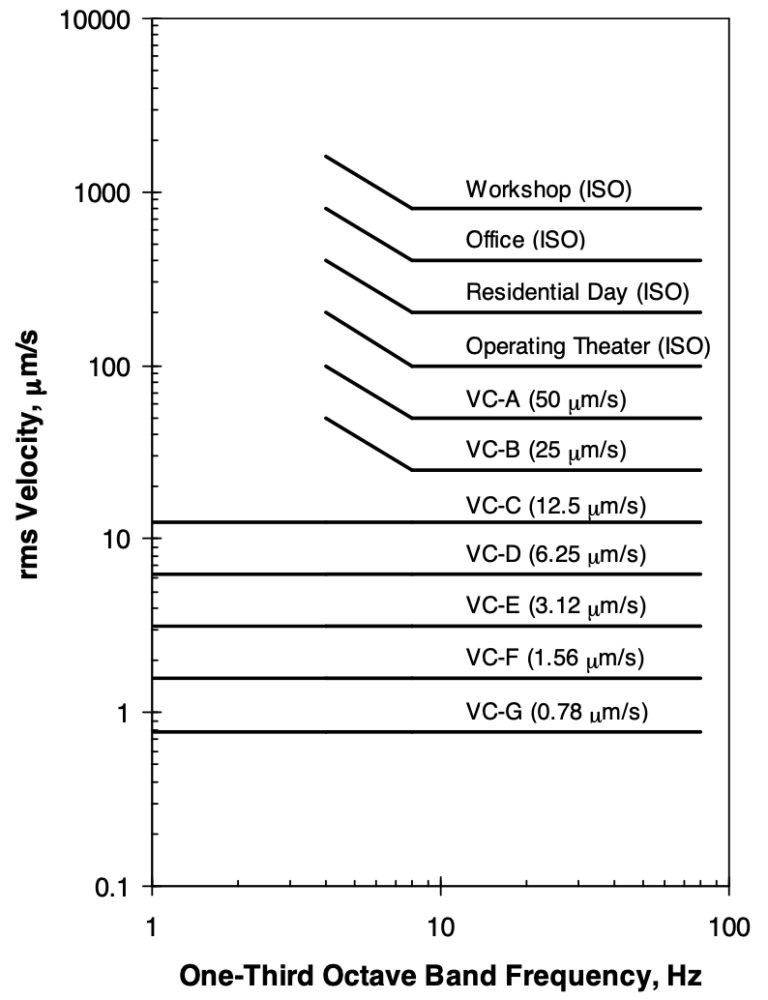
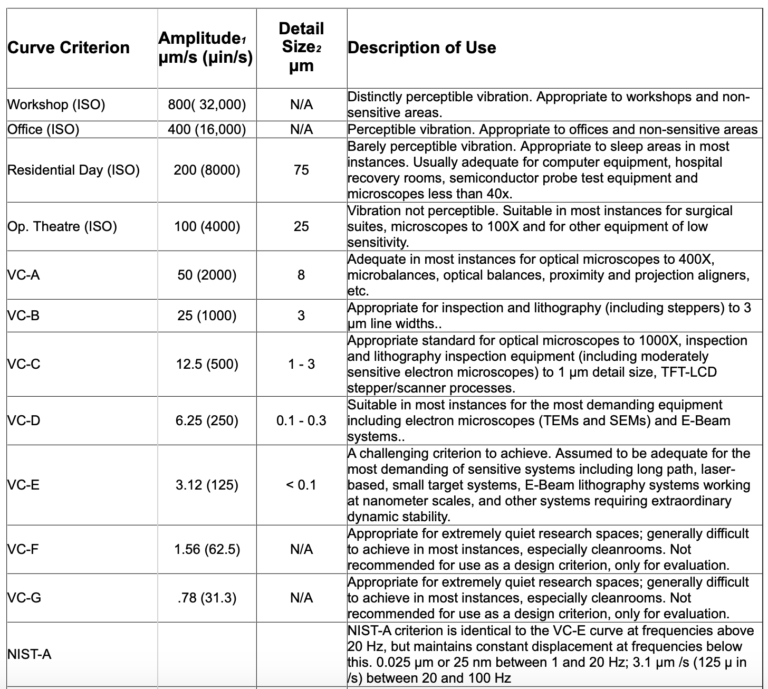
As the table shows, there are floor standards that are ideal for certain metrology applications. Keyence recommends that the floor under a VK-X laser confocal microscope be VC-C. The 50x objective of the VK microscope provides 1000x magnification which would place it in the VC-C category in the table above.
At Peak Metrology we have the equipment and software that it takes to measure the floor vibration. Whenever we perform benchmark testing with our larger travel stages and VK-X microscopes from Keyence we also capture the floor vibration levels to paint the full picture for the user.
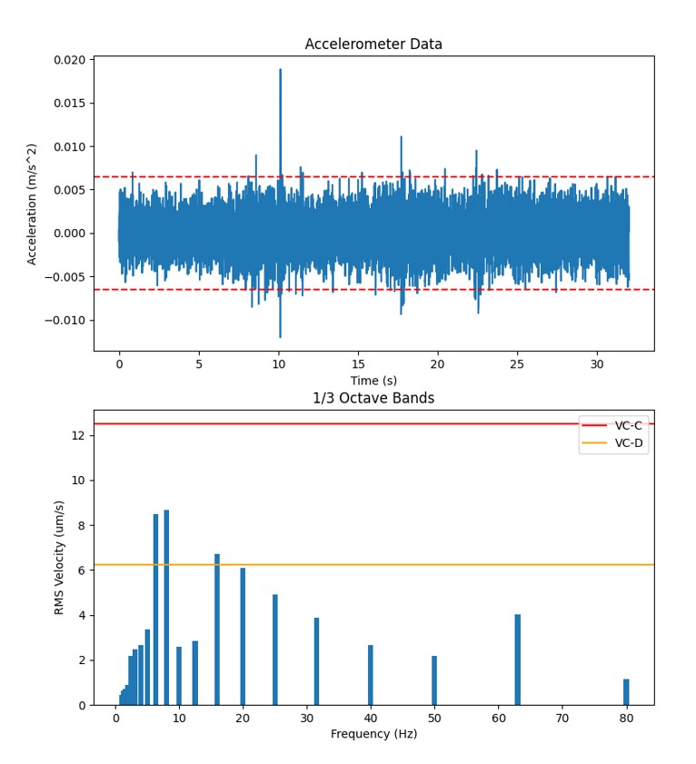
Showing the raw accelerometer data (upper left) and two vibration curves. The data is broken up into frequency ranges and then plotted to show the magnitude across the spectrum. This plot shows that the floor being measured does not meet VC-D levels but it does meet VC-C levels because all of the blue bars are below the VC-C criteria curve.
Impact on larger travel positioning equipment
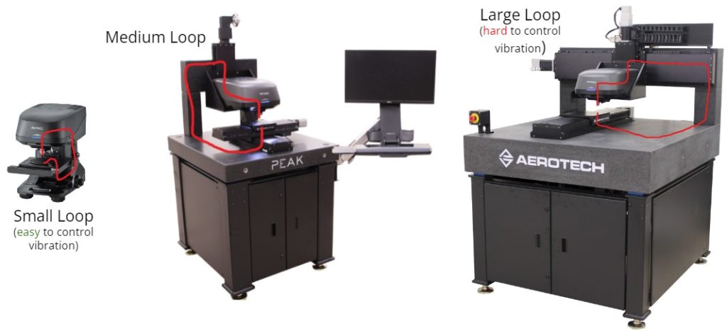
For users interested in larger travel XYZ stage motion, the floor vibration is even more important to understand and control. This is where Peak Metrology has performed a significant amount of analysis in order to counteract the impacts of floor vibration through equipment design. In general, the larger the machine the more the vibration will be amplified unless certain precautions are taken. This is because the mechanical distance between the microscope objective and the part increases. This is called the metrology loop.
Options to improve vibration stability
There are ways to improve the vibration performance of a VK-X laser microscope while also reaping the benefits of a larger travel stage system.
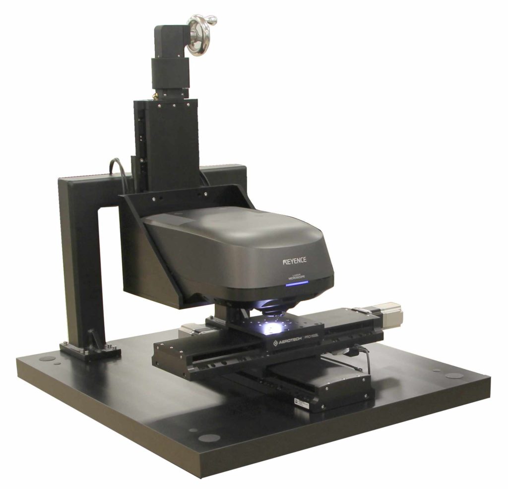
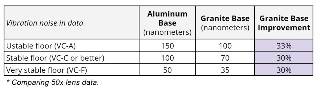
Option #1 – Use a granite base
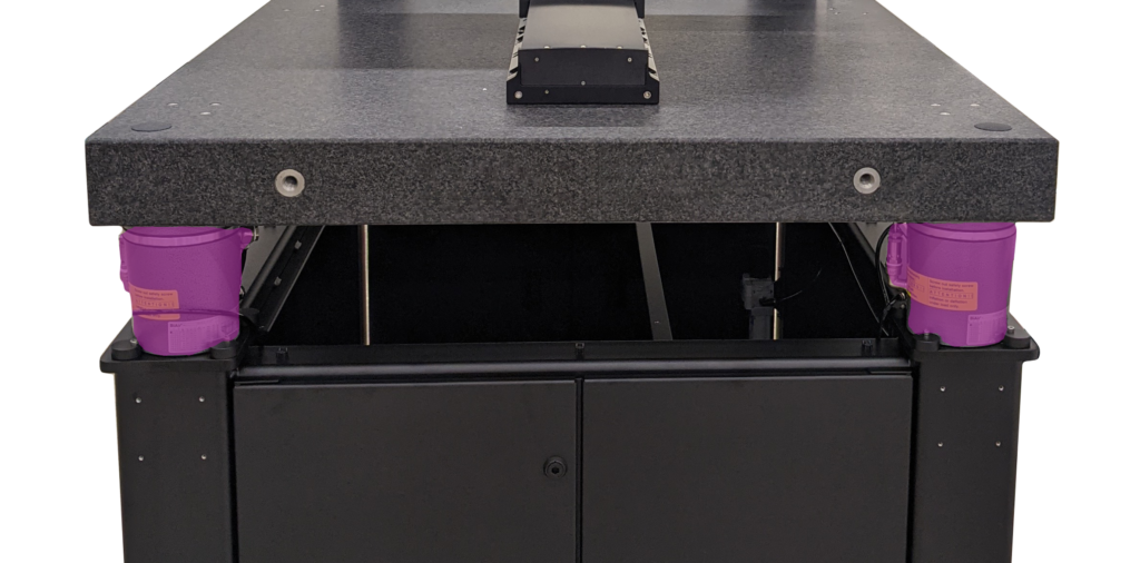
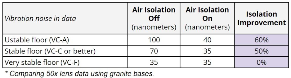
Option #2 – Use an air isolation system
Passive air isolation systems will reduce the influence of vibration at the microscope head. Once the underlying floor is good enough, there are much fewer vibrations for the air isolation system to compensate for. Air isolation systems require only a single airline. However, they do add cost to the equipment. If performance is important, the use of an air isolation system is recommended.
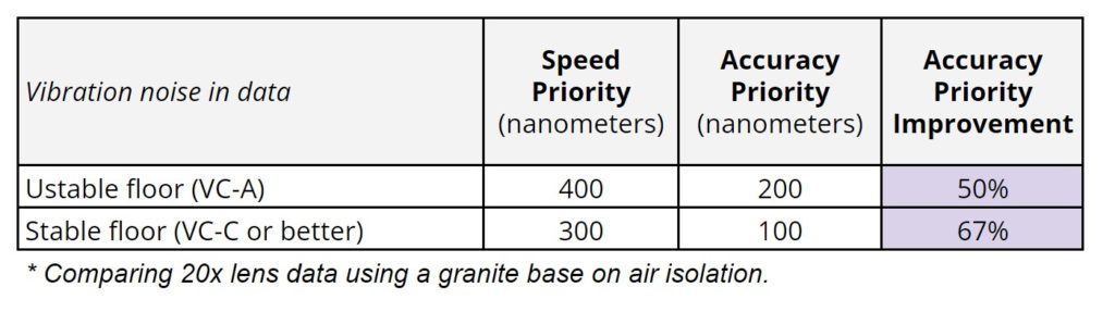
Option #3 – Use accuracy priority (For 20x magnification lenses)
Laser confocal microscopes use an internal Z stage to scan the objective through the focal depth specified by the user. This motion causes vibrations similar to floor vibrations, but in reverse. With the Keyence VK-X laser microscope, there is a simple setting that allows for extra time in the measurement to account for vibration errors caused by the fast-moving objective stage. This mode is called Accuracy Priority. Its counterpart, Speed Priority, offers faster measurement times at the expense of vibration levels. The 50x lens automatically uses Accuracy Priority while the 20x lens defaults to Speed Priority.
Conclusions
Floor vibration levels have a direct impact on vibration artifacts that show up in the measurement data. This is amplified on larger travel stages. However, if the right precautions are taken, the measurement performance can be maintained. Large travel positioning and high fidelity measurements can be made on the same piece of equipment, and they can work together on a variety of floor vibration levels.
For more guidance and consultation on selecting the right positioning system reach out to us.